Device Setup
Once the device has been mounted and an appropriate power source has been identified, it is ready to be set up and configured.
Sensor & Power Connections
One physical connection is required for power, and one for the main
sensor (Cam1). If a second sensor (Cam2) is required, that may also
be connected. To connect the sensor and power to the Slamcore Aware
device, follow these steps:
- Screw in the Wi-Fi antennas to the
ANT1andANT2connectors. - Connect the FAKRA cable between the sensor and the port labelled
Cam1of the compute. - If using a second camera, connect the FAKRA cable between the second
sensor and the port labelled
Cam2of the compute. - Check that the protection film on all connected sensors' lenses have been removed.
- Next, connect the compute box to a power supply, either provided by
the vehicle or an external battery source (See Power Requirements
for details). The red
PWRLED will start blinking and the device will power up automatically. - Wait up to 5 minutes for the device to fully power on and the web interface to become accessible.
The sensor unit(s) must be connected to the device before providing power for correct initialization. If a sensor unit is connected whilst the device is already powered on, please reboot the device using the
REBOOT DEVICEbutton in the settings page of the web interface, as explained in Device Reboot & Shutdown.
Setting the Vehicle dimensions and center position
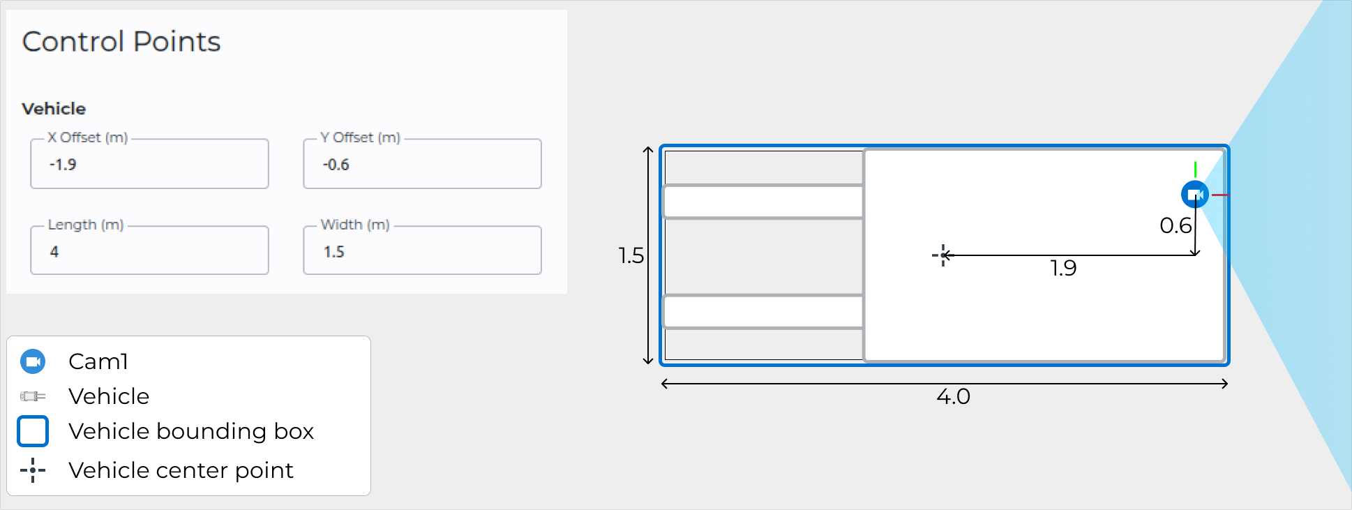
The footprint of the vehicle is represented in the system as a bounding
box defined by the vehicle width and length. With the requirement of
Cam1's forward direction (its x axis) to be aligned with the
forwards/backwards direction of the vehicle, the Length parameter
defines the size of the bounding box along the x axis, and the Width
parameter defines the size of the bounding box along the y axis. The
position of the bounding box is defined as the position of its center
relative to Cam1, and is set via the X Offset and Y Offset
parameters. See the figure below for an example vehicle set up.
Changing the Vehicle Tracking Point
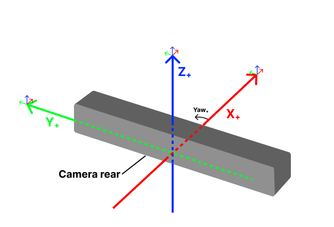
By default the system reports the vehicle's pose with respect to the map
as the pose of the main Slamcore Aware sensor unit (Cam1): the default
tracking point is on the underside of the unit casing, centered on the
threaded mount point, and the orientation convention is as specified in
the figure below. This is the default vehicle tracking point used by the
system. The tracking point can be changed to another point on the
vehicle by applying an offset relative to the Slamcore Aware sensor
through the web interface settings, indicating the position and
orientation offset of the tracking point from the sensor unit:
-
On the web interface, select
 Settings from
the left panel > POSITIONING tab and scroll to the bottom of
the tab for the Tracking Point input fields under the Control
Points section.
Settings from
the left panel > POSITIONING tab and scroll to the bottom of
the tab for the Tracking Point input fields under the Control
Points section.
Tracking Point Input Fields -
Input the offset values to transform the tracking point from the sensor unit sensor frame to the required position, following the axes convention provided by the diagram above.
For example:
X = -3.0sets the tracking point 3.0 m behind the sensor,Y = -2.0sets the tracking point 2.0 m to the right from the sensor, andYaw = 180°rotates the tracking point around the Z-axis, resulting in the X-axis pointing in the opposite direction to the sensor unit sensor. For example, if the sensor is mounted facing backwards on the vehicle.

Tracking Point Input Example noteShould you need to reset to the default values, set input field values to
X = 0.0,Y = 0.0andYaw = 180.0 -
Select SAVE CHANGES on the POSITIONING tab inside to the Control Points section to apply your settings.

Control Points Saved -
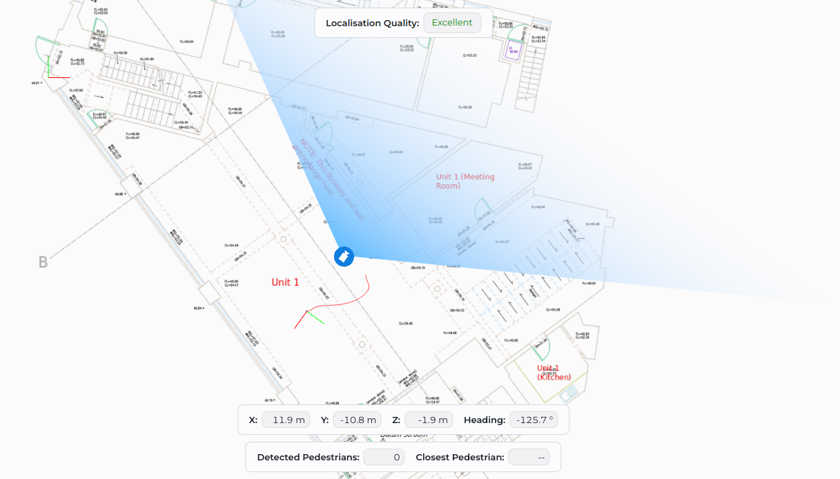
The poses will now be published from the specified tracking point, indicated by the 3D axes which is now at a different location from the camera icon.
Tracking Point Visualisation
Configuring the second sensor (Cam2)
If a second sensor is connected to the device, its pose on the vehicle
relative to Cam1 must be set through the UI:
1. On the web interface, select Settings from
the left panel > POSITIONING tab and scroll to the Cam2 input
fields under the Control Points section.

-
Input the offset values to define:
- the position of the sensor relative to the
Cam1sensor unit 1/4′′ thread hole, and - the yaw of the sensor relative to the
Cam1sensor unit forward direction, following the axes convention provided by the example below, where: X = -0.9sets theCam2position 0.9 m behind theCam1sensor,Y = -0.4sets theCam2point 0.4 m to the right of theCam1sensor, andYaw = 180°rotates theCam2point around the Z-axis (Up), resulting in the X-axis pointing in the opposite direction to theCam1sensor.
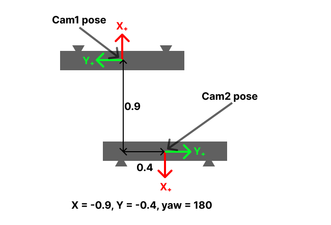
Cam2Pose Example (top-down view)
Cam2Pose Input Example - the position of the sensor relative to the
-
Select SAVE CHANGES on the POSITIONING tab inside the Control Points section to apply your settings.

Cam2Saved
Configuring Alert (requires Alert license)
Alert is enabled via the toggle on the ACCESSORIES tab in the
Settings page. This tab also contains a toggle
to enable/disable the beacon buzzer. Note that only one of the two
beacon ports will switch the buzzer on; if using only one beacon users
should ensure they connect it to this port.
On the POSITIONING tab, the user can set the alert zone Danger and Caution distance thresholds: When the vehicle is moving, the zones around it that are checked for pedestrians adapt to the vehicle's velocity. These values set thresholds on proximity to the vehicle in these zones that configure the alert to be at Caution or Danger level.
Default Network Connection
To access the device web interface for configuration and monitoring, a network connection must be established between the Slamcore Aware device and your computer.
The following network interfaces are available:
-
Wi-Fi:
- Each new Slamcore Aware device will start its own Wi-Fi access point / hotspot. This enables direct connection to the device over Wi-Fi. Alternatively, the device can also be configured to join your facility's Wi-Fi network.
-
Ethernet:
- An Ethernet port on the device enables direct connection with a computer or, alternatively, to a regular wired network running a DHCPv4 server.
The sections below will cover how to connect to the device through either its Wi-Fi Hotspot or using a direct Ethernet connection, for initial device setup. Instructions on how to change the default network settings and connect the device to your facility's local network are provided later on in the Local Network Connection section.
Wi-Fi Hotspot Network Connection
The default out of the box Wi-Fi configuration for each device is access point / hotspot mode. In this mode, the device will host its own Wi-Fi network, enabling easy direct wireless connection to the device. It is also possible to change the default mode and connect the device to your facility's network, this is covered later in the Local Network Connection section.
To connect your computer to the device using its hotspot network,
- Identify and select the device's network under your computer Wi-Fi
settings:
- Hotspot Network Name:
sc-aware-<device-ID>-hotspot - Hotspot Password:
sc-aware-<device-ID>
- Hotspot Network Name:
<!-- -->
- Access the Slamcore Aware web interface for the device via a web browser using the default hotspot IP address - 192.168.42.1 .
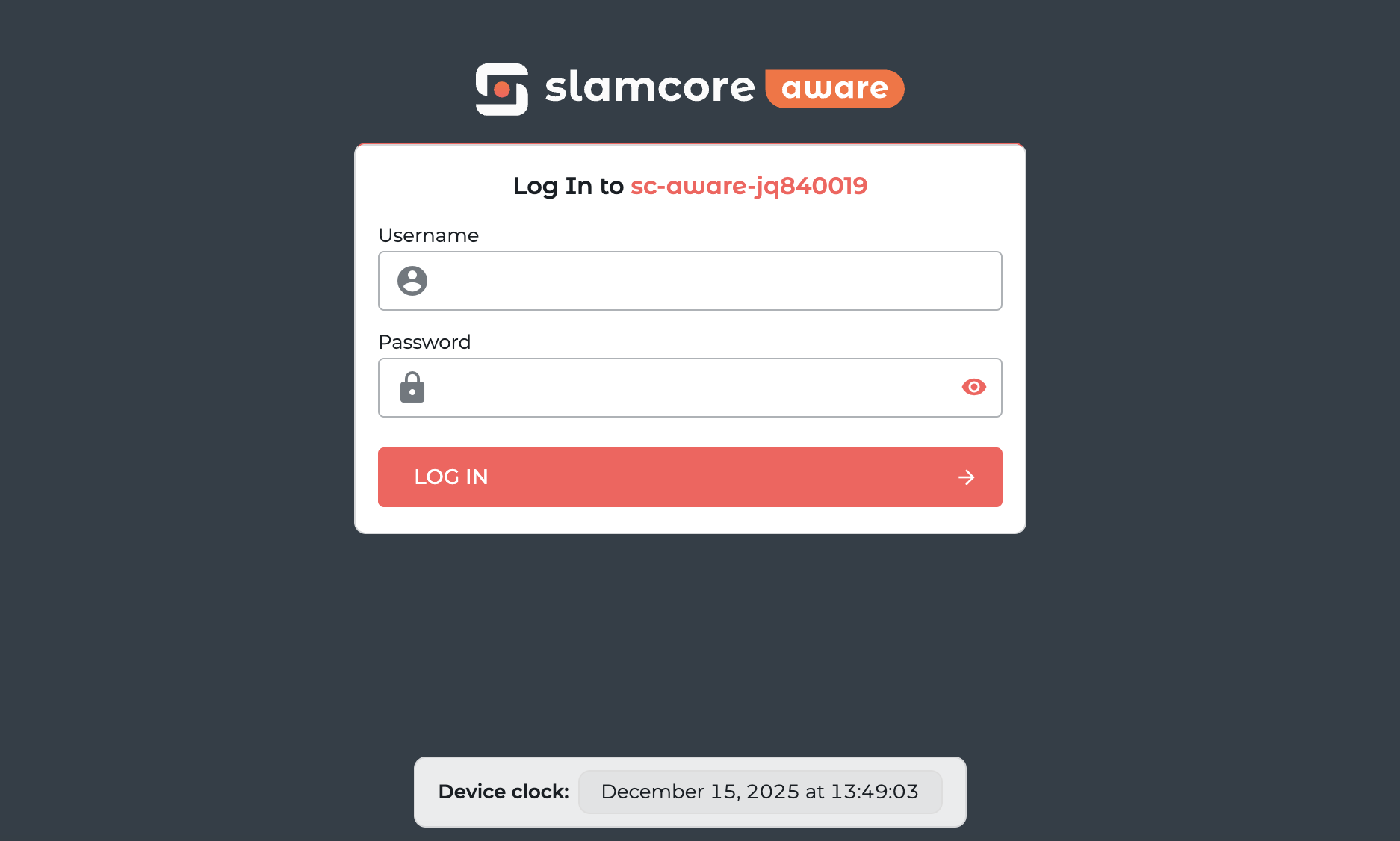
- You will be presented with a login page - enter the login details provided by Slamcore.
To connect to a different device, connect to the hotspot network of the other device and follow the same steps.
If you have successfully accessed the web interface using the Wi-Fi hotspot you may skip the next section, which covers an alternative approach using Ethernet.
The first things to do before you start using the device are
- (If specified by Slamcore) updating the software, and
- Updating the license file.
These steps are covered in the sections below.
Direct Ethernet Network Connection
It is also possible to connect to the device over Ethernet. The device
has a static Ethernet IP address (169.254.1.1) through which the web
interface can be accessed when connecting an Ethernet cable directly
between the device and a computer. Alternatively, you can connect the
device to a wired network running a DHCP server, where it will get
assigned an IP address by the router.
To connect the device directly to your computer and access its web interface,
- Connect an Ethernet cable between the device and your computer.
<!-- -->
- Configure the network settings on your computer following the instructions in the table below depending on your operating system.
Network Configuration for Direct Ethernet Connection
| Operating System | Network Settings |
|---|---|
| Ubuntu | Access the Wired Network connection settings in Network Manager. Go to the IPv4 tab and set the IPv4 Method to Link-Local Only. Apply the settings.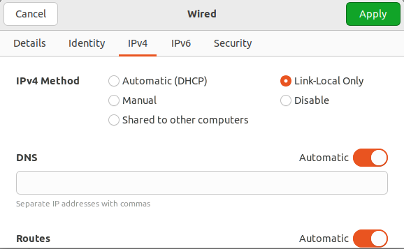 |
| Windows | No configuration is required. Simply connect an Ethernet cable between the device and your Windows computer, wait up to 30 seconds for the connection to be established. |
| macOS | No configuration is required. Simply connect an Ethernet cable between the device and your Mac, wait up to 30 seconds for the connection to be established. |
- Wait up to 30 seconds for the connection to be established. Then access the Slamcore Aware web interface for the device via a web browser using the default Ethernet IP address - 169.254.1.1. If this does not work, please see Troubleshooting for details on how to connect over Ethernet using a static IP address on your computer.
- If the connection was established successfully, you will be presented with a login page - enter the login details provided by Slamcore.
Once you have access to the web interface, the first things to do before you start using the device are updating the software and the license file.
Software Update
After receiving a new unit, a software update may be necessary. This may
be an app update (.tbz2 file type) or full system update package
(.raucb file type) depending on the contents of the release.
The MK2 and MK3 devices use the same app update package (.tbz2 file
type), but different system update packages (.raucb file type).
To update the device with either types of packages:
- Download the software update package provided by Slamcore.
- In the web interface, go to Settings > General > Upgrade
Software > click on Choose file and select the software
update package, e.g.
slamcore-webui_jetson_arm64_0.x.x.tbz2
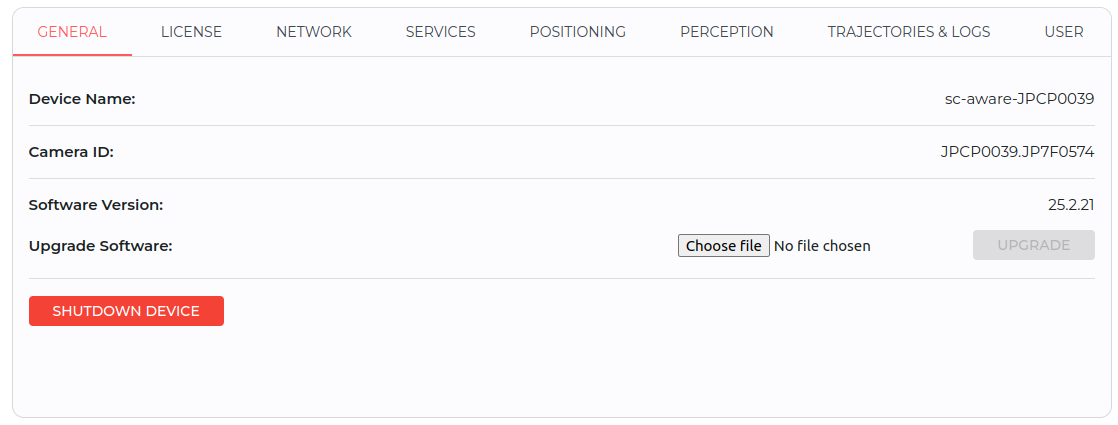
- Click
UPGRADEto start the update. Slamcore Aware App updates may take up to 15 minutes to complete, whilst full Slamcore Aware system updates may take longer.

- A final pop-up notification will appear once the upgrade has been successful.

License Update
The license file on the device will need to be updated manually upon receipt of the Slamcore Aware device.
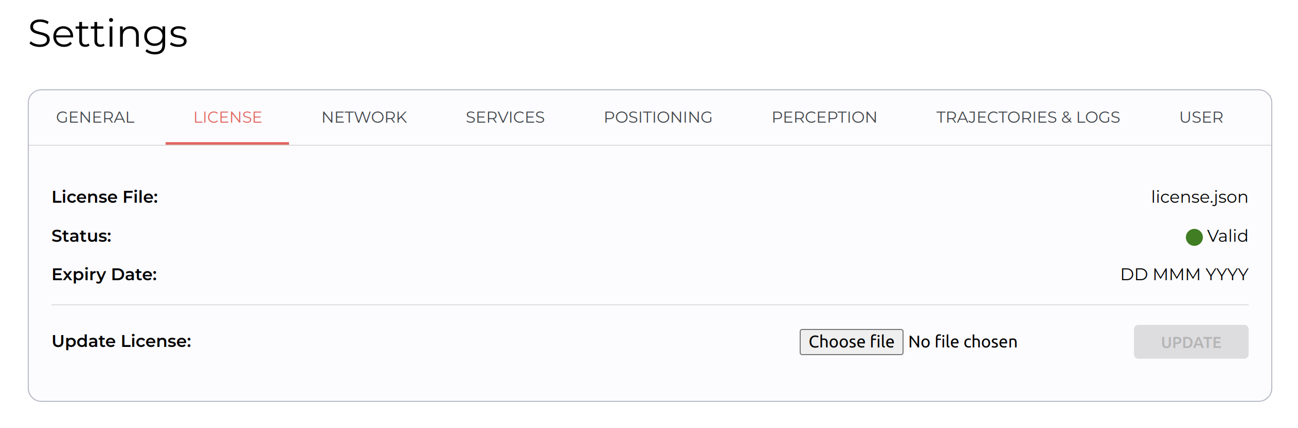
Download the license file (.json file type) provided to you. On the
web app, go to Settings > General > License > Update
License > Choose file and select the license file. Then click
UPDATE to update your Slamcore Aware license.
Device Reboot & Shutdown
The Slamcore Aware device provides options to safely reboot and shutdown the device.
To reboot from the web interface, go to
Settings > General and click Reboot device. Confirm the
hostname shown in the dialog before applying the reboot.
On versions prior to v25.07, avoid using the REBOOT DEVICE button in
the web interface due to a known issue where it may shut down the
device instead of rebooting it.
The physical RESET button on the outside of the device can also be
used to reboot the device, as explained in Hardware Interfaces. A 3
seconds press of the RESET button will force shutdown the device and
then reboot the device if external power is connected.
If the device does not reboot successfully and can not be reached over Wi-Fi or Ethernet, you will need to remove the power connector and wait for the device to shut down fully (up to 4 minutes) before reconnecting power.
If power is disconnected from the device, it will automatically enter a
3 minute grace period during which the device operates as normal. If
power is restored during this time, the device will continue to run in
normal operation mode. If power remains disconnected, at the end of the
3 minute grace period, the device will automatically stop the ongoing
run and save map updates and run data before shutdown. When shutdown is
complete, the Power LED will be turned off. There is no need to press
the physical RESET button to power off the device.