Hardware Interfaces
The Slamcore Aware compute unit is equipped with a number of buttons, LEDs and ports to provide multiple options for data transfer and communication with other systems.
MK3 Compute Unit
Overview of interfaces
The sides of the device will be referred to as top, bottom, N, S, E, W - with W being to the left of the Slamcore logo icon and E being to the right of the slamcore logo text when looking at the device from the top.
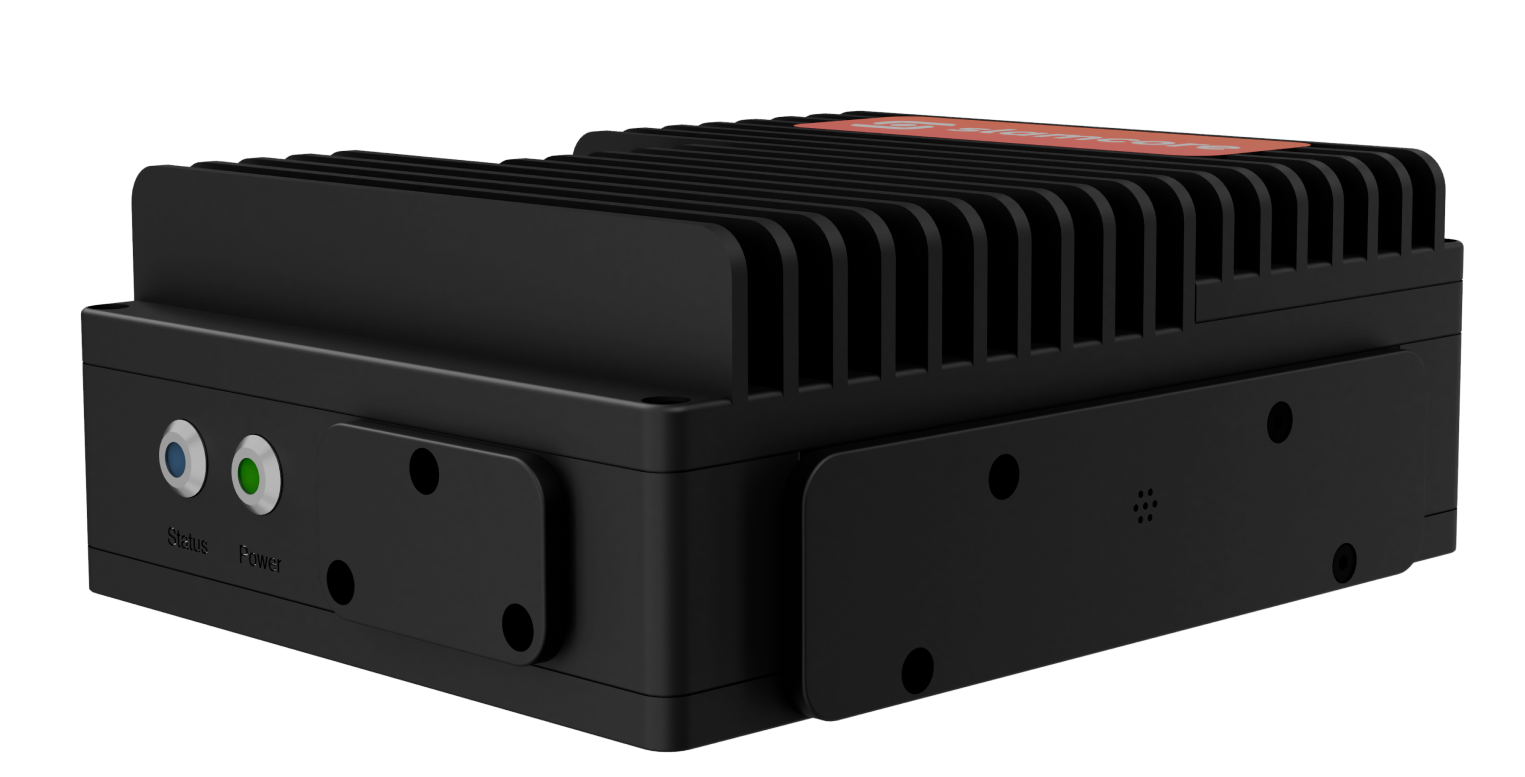
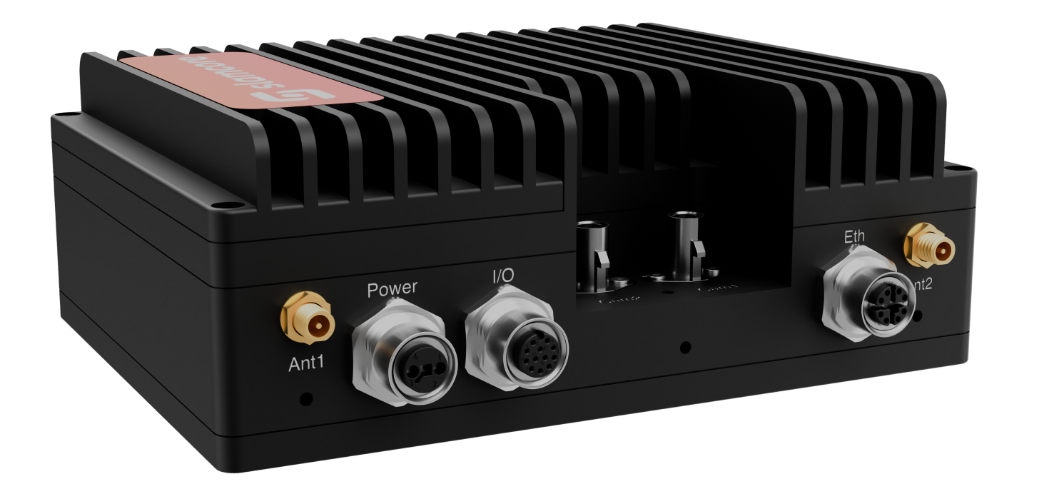
Side Interfaces and markings
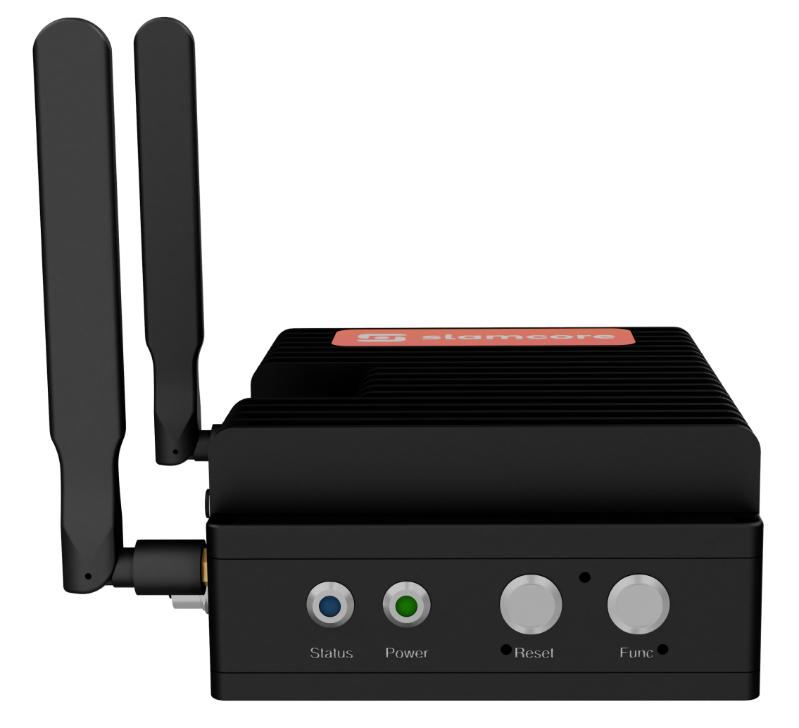
The S face contains:
S face interfaces
| Label | Interface | Description |
|---|---|---|
| RESET | Button | Controls power state of device. See the Buttons & LEDs (MK3) section below for details. |
| FUNC | Button | Reserved for future use. |
| STATUS | Blue LED | Reserved for future use. |
| PWR | Green LED | Indicates power state of device. See the Buttons & LEDs (MK3) section below for details. |
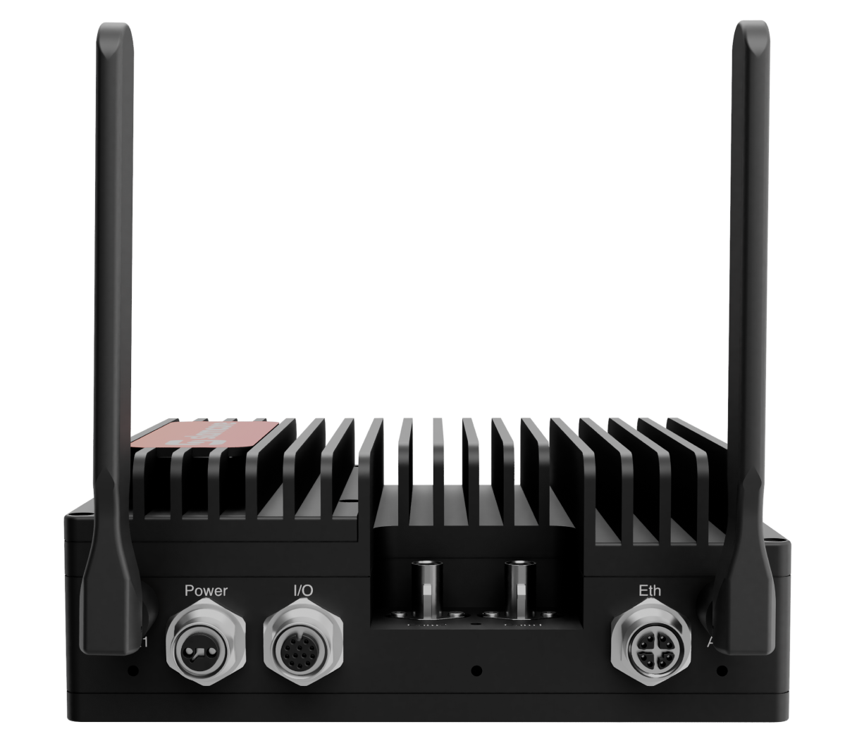
The W face contains:
W face interfaces
| Label | Interface | Description |
|---|---|---|
| POWER | M12 circular connector, T coded | Provides power to the device. See Power Requirements for details on the power supply and power cable requirements. |
| ANT1 | RP-SMA Female | For RP-SMA male Wi-Fi antenna. |
| ANT2 | RP-SMA Female | For RP-SMA male Wi-Fi antenna. |
| IO | M12 circular connector, A coded | For GPIO and CAN communication |
| ETH | M12 circular connector, X coded | For network connectivity if not using Wi-Fi. |
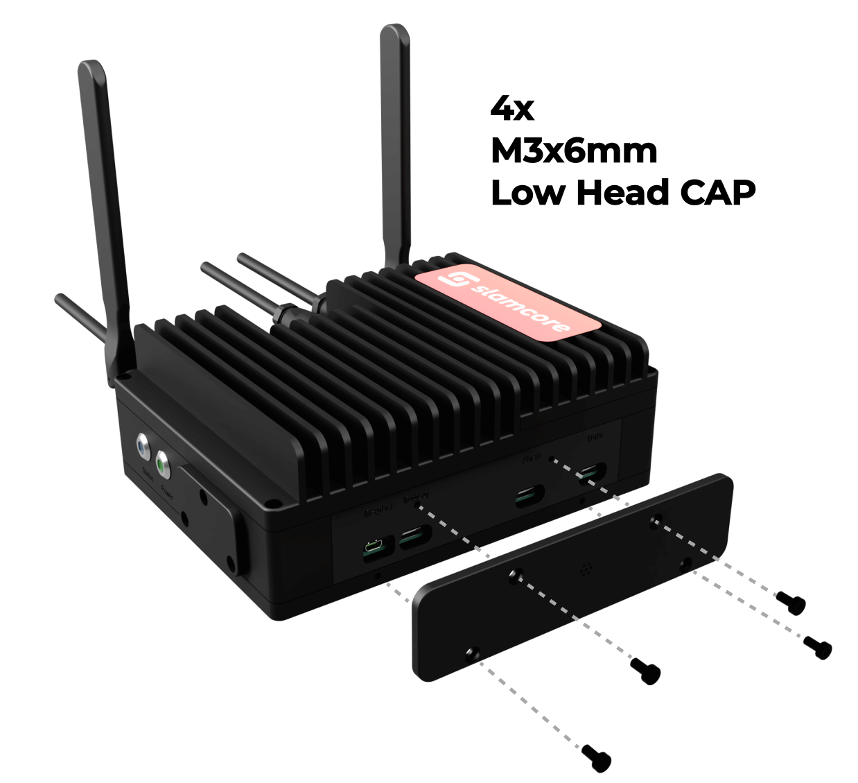
IP65 rated port cover
To access interfaces on the east face the IP65 rated port cover must be removed. This should not be removed unless necessary and on a temporary basis. It must be replaced after use to maintain the IP65 rating of the device. Take care that the sealing surface and O-ring seal are clean and free from debris before replacing the cover.
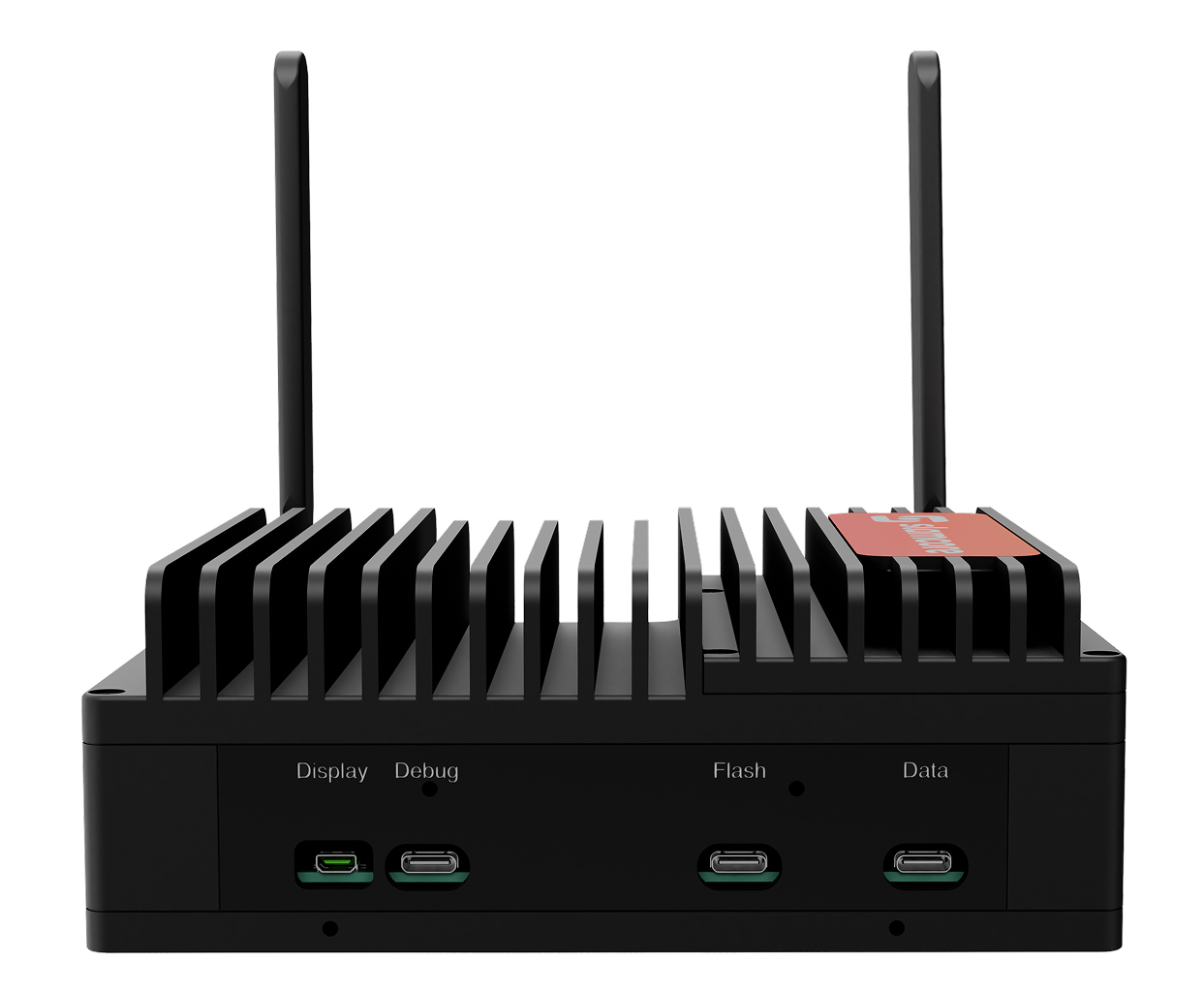
The E face contains:
E face interfaces
| Label | Connector | Description |
|---|---|---|
| Display | HDMI | Currently not supported, reserved for future use. |
| Debug | USB-C | For Slamcore use only. |
| Flash | USB-C | For Slamcore use only. |
| DATA | USB-C | For data export from the web interface to an external SSD. See Export to external drive for more details. |
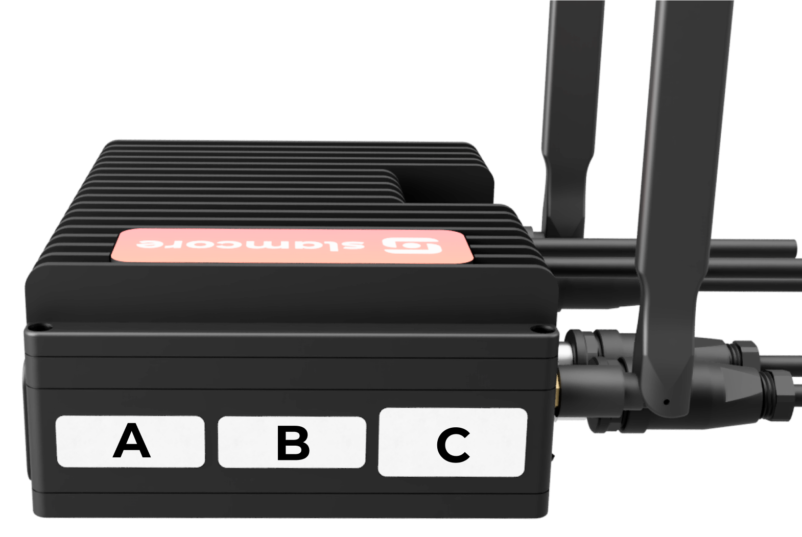
The N face contains no ports, it contains the following markings:
N face markings
| Label | Title | Description |
|---|---|---|
| A | Serial/Part number | Contains the device serial number (SN) and part number (SC PN). |
| B | Mac address | Contains the Ethernet (ETH) and Wi-Fi (WIFI*) MAC addresses. |
| C | Device information | Contains information on the device model, power input and certifications. |
Top & Bottom Interfaces
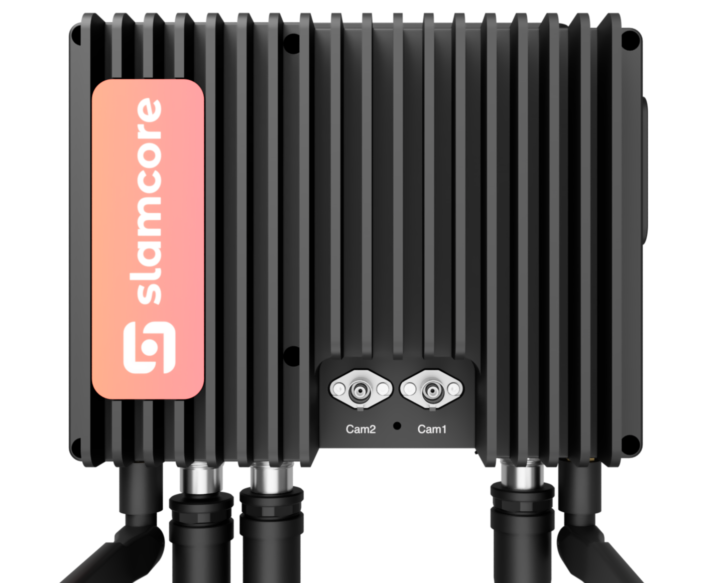
The Top face contains:
Top interfaces
| Label | Type | Description |
|---|---|---|
| Cam2 | FAKRA connector | For connection with the Slamcore Aware sensor unit. FAKRA cable provided with the Slamcore Aware kit |
| Cam1 | FAKRA connector | Please note: When using a single sensor unit, Cam1 must be used. For connection with the Slamcore Aware sensor unit. FAKRA cable provided with the Slamcore Aware kit |
The Bottom face contains no interfaces.
Cable interfaces
Detailed cable information is provided in the figure below and in the linked MK3 external cable diagrams.
All cables used to connect to the Slamcore Aware compute unit can be ordered from Slamcore, length options are specified in the linked diagrams. The standard FAKRA cable is supplied as 3m in length.
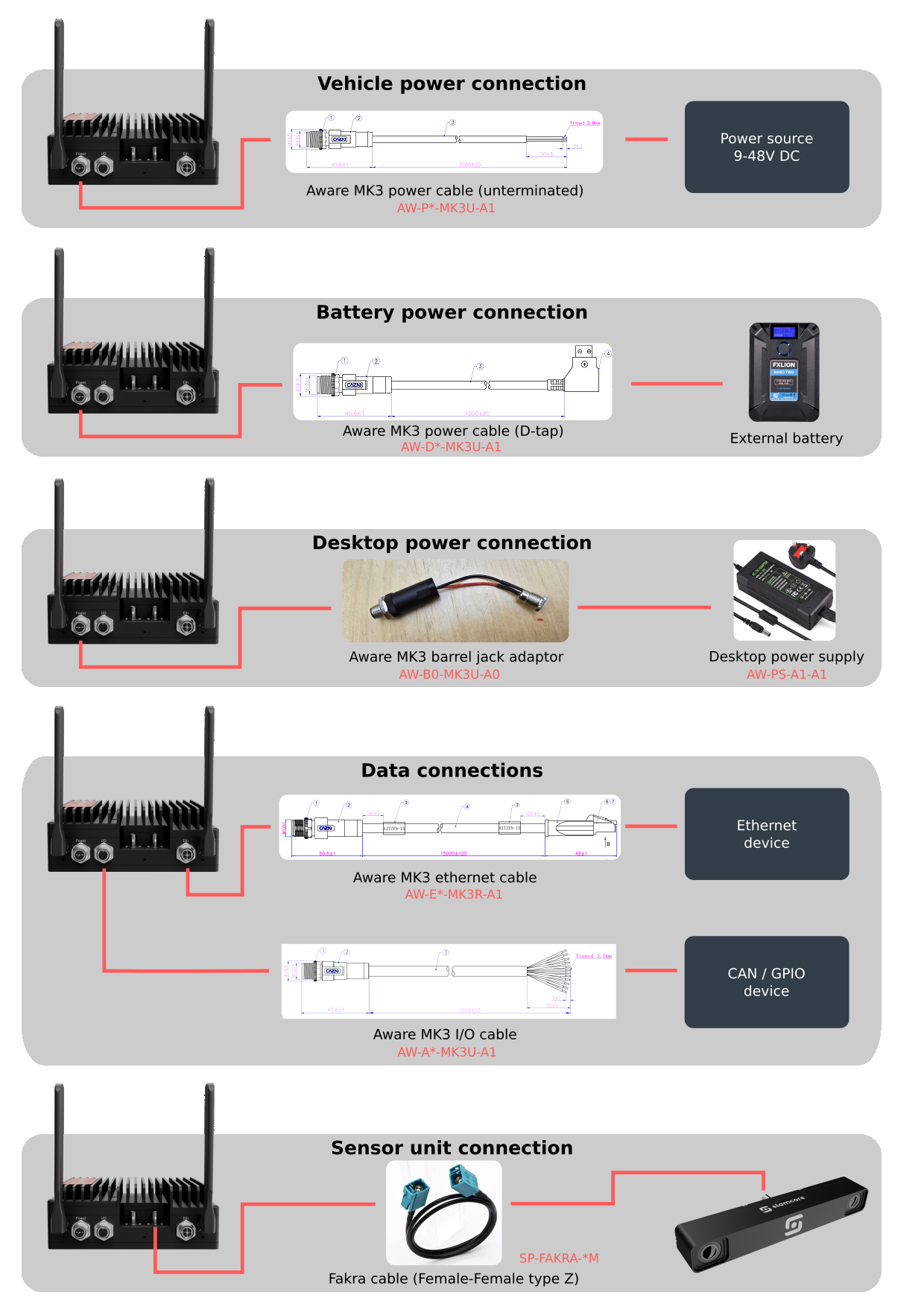
Buttons & LEDs (MK3)
The Slamcore Aware compute device (MK3) has two buttons (Reset and
Func) and 2 LEDs (Power and Status) on the South face to allow the
user to perform a number of actions and monitor the state of the device.
The Status LED and Func button are currently unsupported and
reserved for future use.
Buttons
Buttons are located behind a cover on the South face of the MK3 compute unit. Remove the cover to access the buttons, and replace the cover after use. It is important that the cover remains present during deployment to avoid tampering.
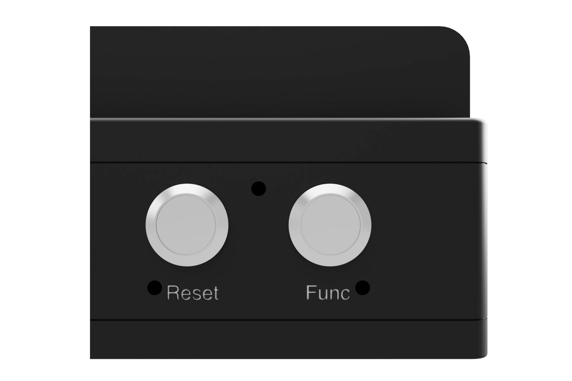
RESET and FUNC buttons on the South face of the MK3 compute unit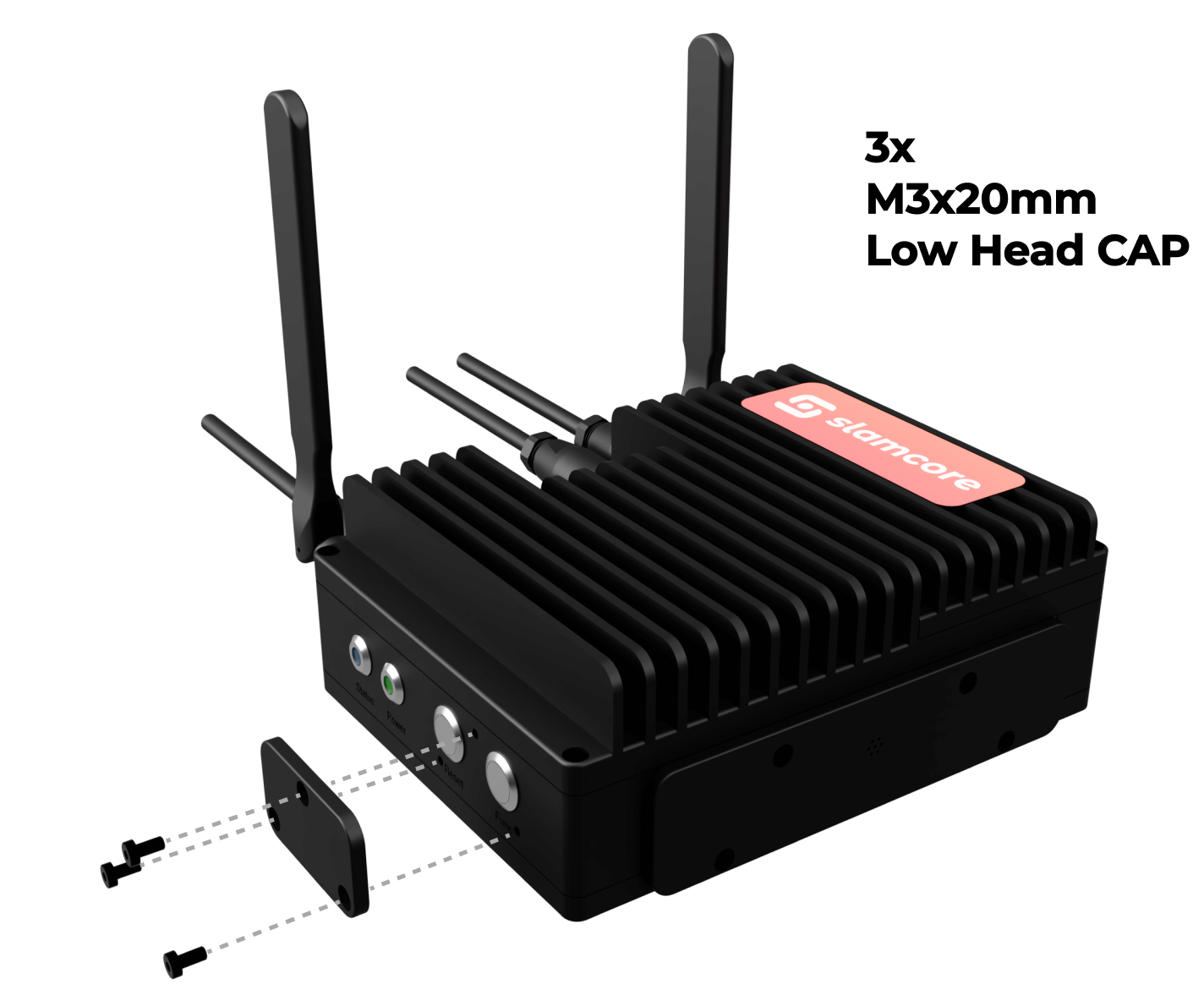
The following actions can be undertaken using the RESET button:
Reset Button Actions
| Button Press | Description |
|---|---|
| <1 second button press | No action. |
| 1 - 10 second button press | Soft reboot device. Enter shutdown sequence and reboot device. If external power is disconnected, device will not restart. |
| 10 - 20 second button press | Hard reboot device. If external power is disconnected, device will not restart. |
| > 20 second button press | For Slamcore use only. Enter Flashing mode. Exit Flashing mode by hard rebooting the device with a 10 - 20 second button press. |
LEDs
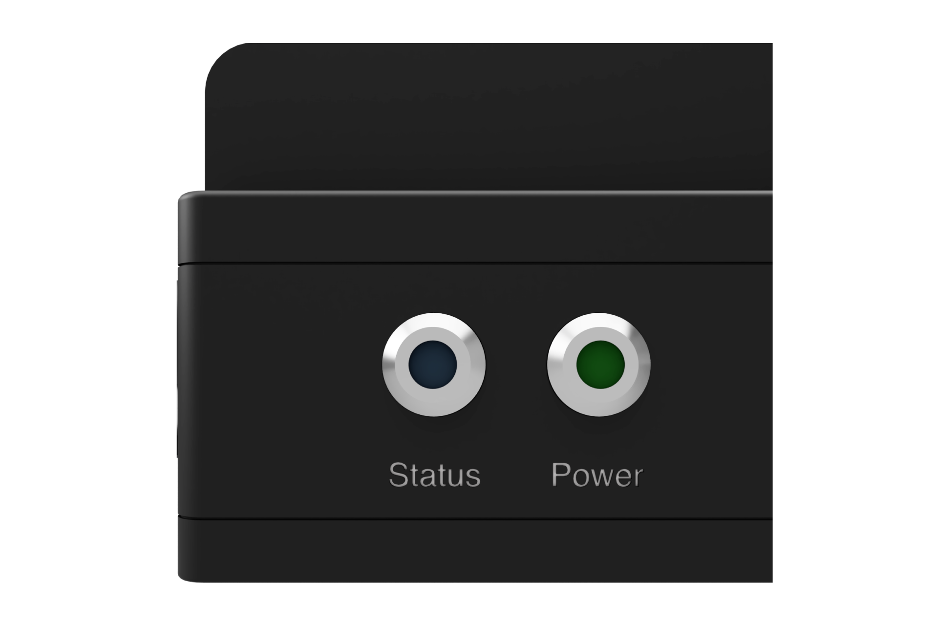
PWR and STATUS LEDs on the South face of the MK3 compute unitThe following states are communicated through the Green PWR LED:
Green PWR LED States
| LED | LED State | Description |
|---|---|---|
| Off | Power is off. | |
 | Breathing 5s ON, 1s OFF | Device powered on and in normal operation, using external power. |
 | Medium blinking 1.5s ON, 0.5s OFF | External power lost and using internal battery power. Entering 3 minute grace period. If power is restored during this time, then device will return to normal operation mode. |
 | Fast blinking (5 Hz) | External power lost and using internal battery power. Grace period expired and initiating shutdown procedure. If the external power is restored, the device will be booted again after completing shutdown procedure. |
Refer to Device Reboot & Shutdown for more information.
MK2 Compute Unit
Overview of interfaces
The sides of the device will be referred to as top, bottom, N, S, E, W - with W being to the left of the Slamcore logo icon and E being to the right of the slamcore logo text when looking at the device from the top.
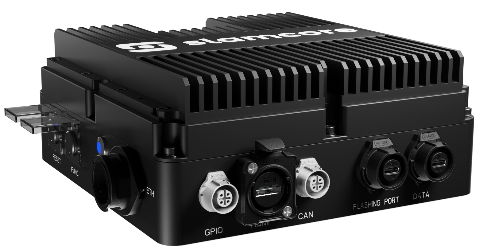
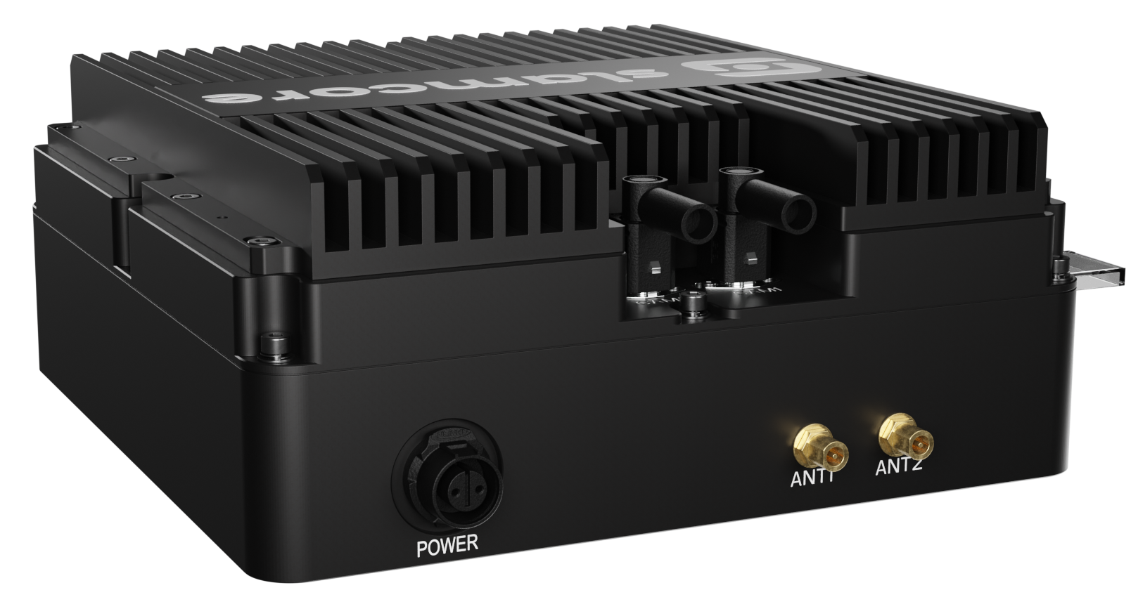
Side Interfaces
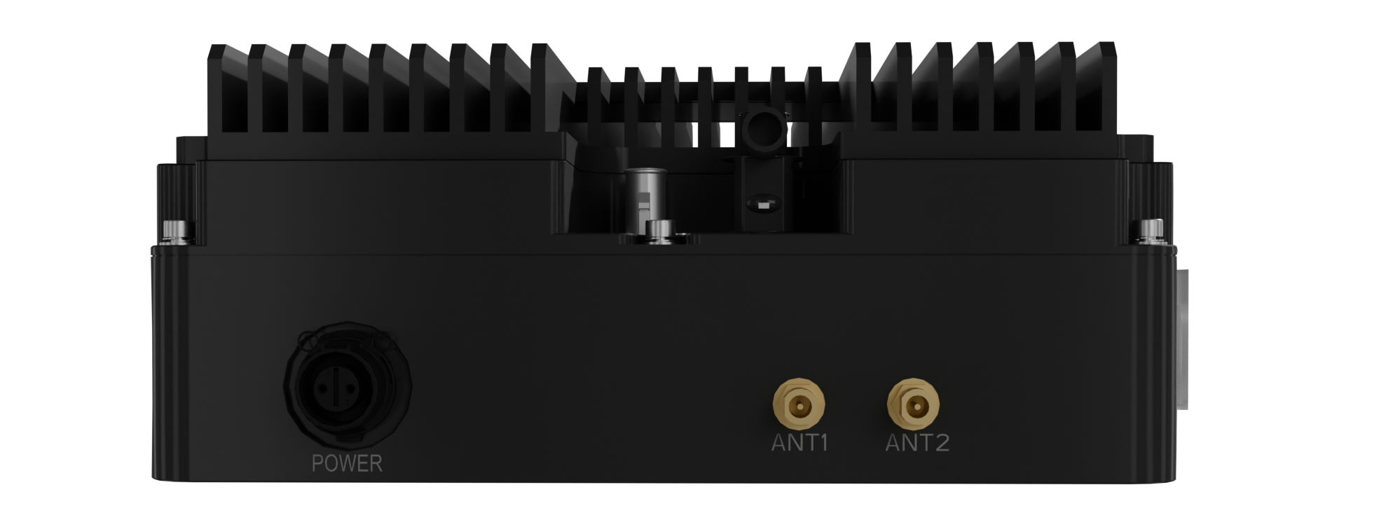
N face interfaces
| Label | Interface | Description |
|---|---|---|
| POWER | Cnlinko LP-12-CO2PE-02-001 | Provides power to the device. See Power Requirements for details on the power supply and power cable requirements. |
| ANT1 | RP-SMA Female | For RP-SMA male Wi-Fi antenna. |
| ANT2 | RP-SMA Female | For RP-SMA male Wi-Fi antenna. |
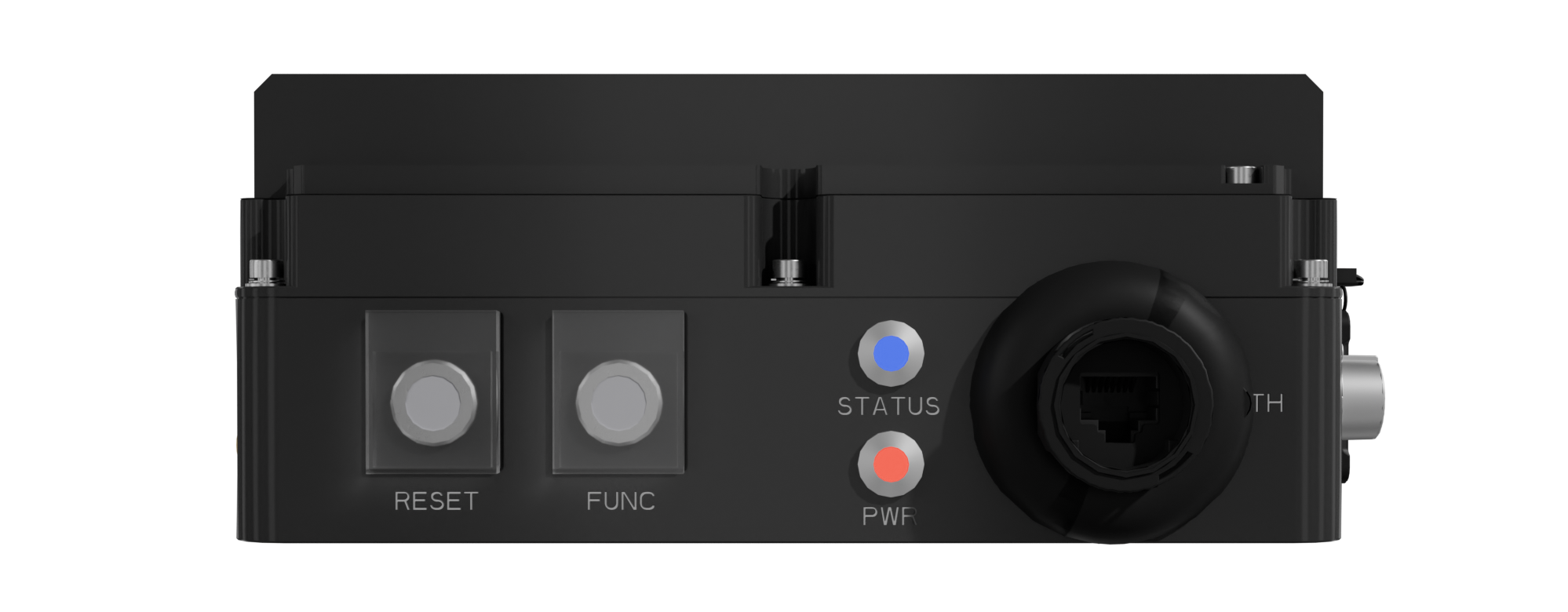
The W face contains:
W face interfaces
| Label | Interface | Description |
|---|---|---|
| RESET | Button | Controls power state of device. See the Buttons & LEDs (MK2) section below for details. |
| FUNC | Button | Reserved for future use. |
| STATUS | Blue LED | Reserved for future use. |
| PWR | Red LED | Indicates power state of device. See the Buttons & LEDs (MK2) section below for details. |
| ETH | Ethernet | For network connectivity if not using Wi-Fi. |
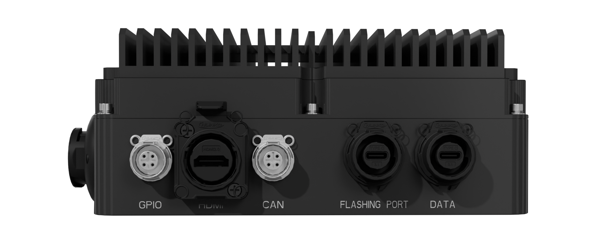
The S face contains:
S face interfaces
| Label | Connector | Description |
|---|---|---|
| GPIO | Cnlinko LP-12-4 | Currently not supported, reserved for future use. |
| HDMI | HDMI | Currently not supported, reserved for future use. |
| CAN | Cnlinko LP-12-4 | Currently not supported, reserved for future use. |
| Flashing Port | USB-C | For Slamcore use only. |
| DATA | USB-C | For data export from the web interface to an external SSD. See Export to external drive for more details. |
The E face contains no ports.
Top & Bottom Interfaces
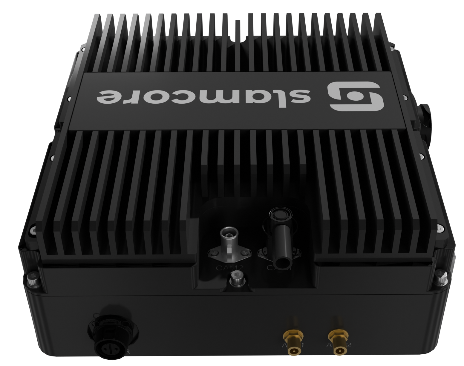
Top interfaces
| Label | Connector | Description |
|---|---|---|
| CAM2 | FAKRA | Currently not supported, reserved for future use. |
| CAM1 | FAKRA | For connection with the Slamcore Aware sensor unit. FAKRA cable provided with the Slamcore Aware kit |
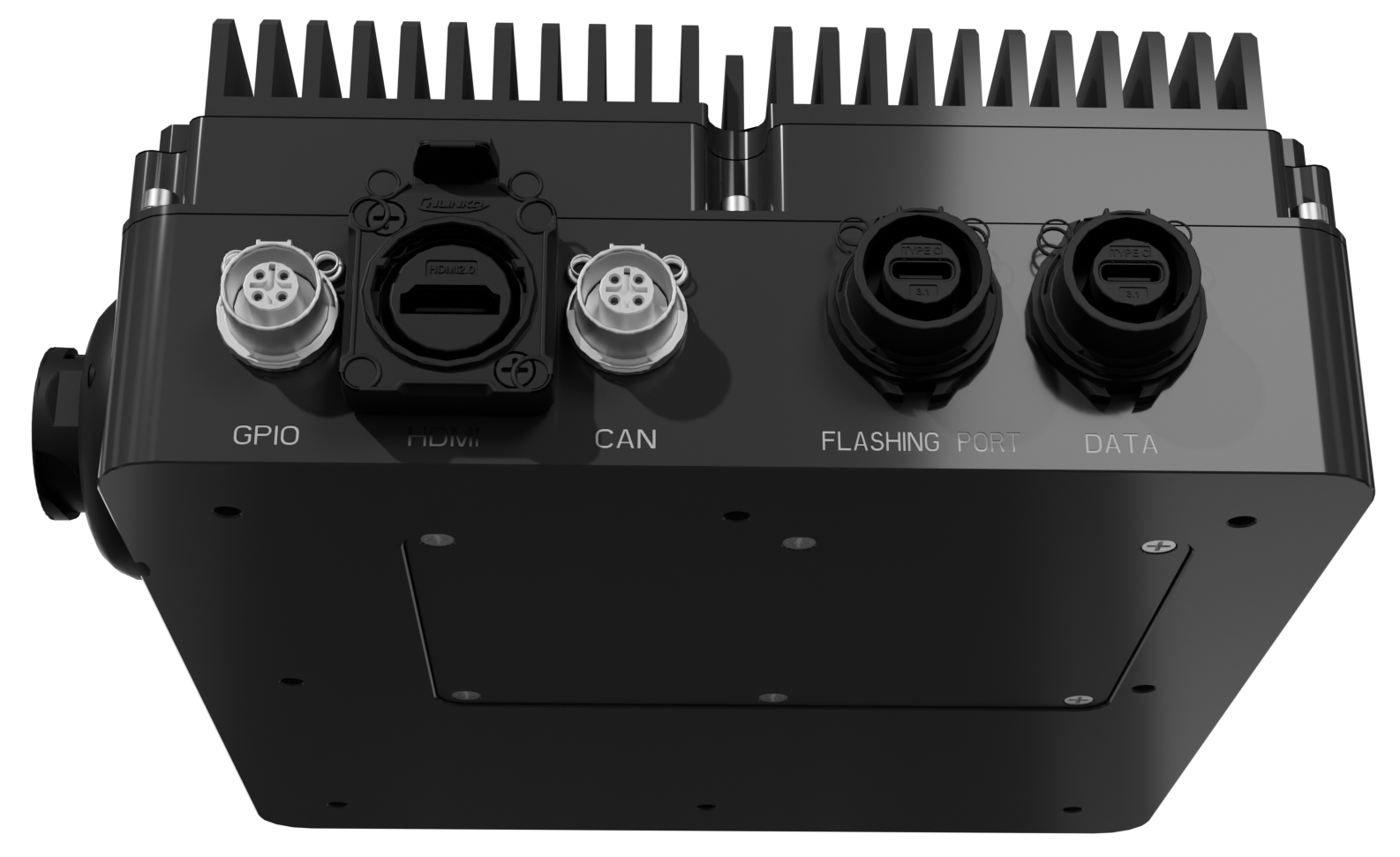
Bottom interfaces
| Label | Specification | Description |
|---|---|---|
| Internal Battery Port | 2x 18650 Li-Ion Batteries. See Power Requirements for full details. | To enable graceful shutdown of the device after sudden loss of main power. |
Buttons & LEDs (MK2)
The Slamcore Aware compute device (MK2) has two buttons (RESET and
FUNC) and 2 LEDs (PWR and STATUS) on the W face to allow the user
to perform a number of actions and monitor the state of the device.
The STATUS LED and FUNC button are currently unsupported and
reserved for future use.
The following actions can be undertaken using the RESET button:
Due to a known issue, please avoid using the Quick button press option to reboot the device. This will shutdown the device instead of rebooting it, and will require manual disconnection of external power, completion of the 3 minute graceful shutdown sequence until all LEDs switch off and, after that, reconnection of external power to boot up the device again.
Please use the 1-5s button press (Hard reboot device) option instead to correctly reboot the device.
Reset Button Actions
| Button Press | Description |
|---|---|
| Quick button press | (Avoid due to a known issue) Enter shutdown sequence and reboot device. If external power is disconnected, device will not restart. |
| 1 - 5 second button press | Hard reboot device. If external power is disconnected, device will not restart. |
| > 5 second button press | Enter Flashing mode, for Slamcore use only. Exit Flashing mode by hard rebooting the device with a 1 - 5 second button press. |
The following states are communicated through the RED PWR LED:
Red PWR LED States
| LED | State | Description |
|---|---|---|
| Off | Power is off. | |
 | Medium blinking (2 Hz) | Device powered on and in normal operation, using external power. |
 | Fast blinking (4 Hz) | External power lost and using internal battery power. Entering 3 minute grace period. If power is restored during this time, then device will return to normal operation mode. |
 | Very fast blinking (10 Hz) | External power lost and using internal battery power. Grace period expired and initiating shutdown procedure. If the external power is restored, the device will be booted again after completing shutdown procedure. |
Refer to Device Reboot & Shutdown for more information.